
How to Conduct a Cleanroom Airflow Visualization Test (Smoke Test)
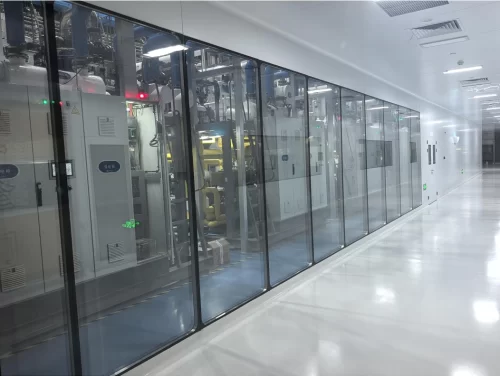
In high-grade cleanrooms—particularly **ISO Class 5 (Grade A)** aseptic filling lines, laminar flow hoods, and semiconductor lithography zones—demonstrating unidirectional (laminar) airflow is a non-negotiable regulatory requirement. An **Airflow Visualization Test**, commonly known as a **Smoke Test**, provides visual evidence that cleanroom air flows uniformly without turbulence, stagnant dead zones, or backflow that could transport contaminants into critical zones.
Mandated by **ISO 14644-3 (Test methods)** and **EU GMP Annex 1**, executing and video-documenting a smoke test is required during initial commissioning, after major HVAC maintenance, and during periodic requalification audits. This technical guide outlines the step-by-step methodology for preparing, conducting, and evaluating a cleanroom smoke test.
1. Regulatory Framework & Core Objectives
The primary purpose of a cleanroom smoke test goes beyond proving that air is moving; it validates that the aerodynamic design effectively protects the product core. The test verifies three fundamental parameters:
- Unidirectional Streamlines: Verifying parallel airflow trajectories from ceiling HEPA/ULPA filters toward low-level wall returns at recommended face velocities (typically 0.36 m/s to 0.54 m/s).
- Turbulence & Eddy Identification: Detecting unwanted vortex formation caused by bulky processing equipment, operator movement, or poor thermal dissipation.
- Pressure Differential Protection: Confirming that air sweeps outward from higher-grade rooms (e.g., Grade A) into lower-grade support zones (e.g., Grade B) when doors or pass boxes are operated.
2. Selecting the Right Smoke Generator (Fogger)
Using improper smoke media can permanently foul HEPA filter membranes or deposit residues on pristine cleanroom surfaces. Always select test media based on cleanroom classification:
| Fog Generator Technology | Media / Mechanism | Cleanroom Suitability & Residue Risk |
|---|---|---|
| Deionized (DI) Water Ultrasonic Fogger | Ultrasonic transducers atomizing DI water or WFI (Water for Injection). | Optimal for ISO 3–5 / GMP Grade A. Zero chemical residue; evaporates completely without contamination. |
| Liquid Nitrogen (LN2) Heavy Fogger | Cryogenic LN2 mixed with hot DI water generating dense white steam. | Ideal for Large Volumes (ISO 5–7). Highly visible, dense fog suitable for video recording across large open spaces. |
| Glycol / Polyhydric Alcohol Smoke (Forbidden in Aseptic Core) | Thermal vaporization of glycol-based fluids. | High Risk. Leaves oily chemical film on surfaces and blinds particle counters; restricted to unclassified or industrial zones. |
3. Step-by-Step Execution Protocol
To produce valid, auditable video documentation, follow a structured 4-phase testing procedure:
Phase 1: Pre-Test Calibration
Verify that cleanroom HVAC systems are fully balanced. Measure supply air velocities at filter faces using a calibrated anemometer to ensure speeds fall within 0.45 m/s ± 20%. Confirm positive pressure cascades between adjacent rooms using differential pressure transmitters.
Phase 2: Static Test State (“As-Built” / “At-Rest”)
Position the fogger wand 150 mm to 300 mm below the FFU face or discharge diffuser. Introduce fog at neutral velocity so as not to disrupt natural air velocity. Observe and record air behavior across the room width and near return air risers.
Phase 3: Dynamic Test State (“In-Operation”)
Simulate realistic production activities: run filling machines, move robotic arms, and have operators perform standard gowning or material handling routines. Introduce fog directly over critical work surfaces (e.g., stopper bowls, vial filling needles) to verify that sweeping action clears particulates rapidly without back-siphonage.
Phase 4: Containment & Door-Opening Challenges
Place fog sources near pass boxes and door thresholds. Open doors per SOP speed and capture video proof that outward positive pressure prevents external air infiltration into the higher-grade room.
Request Cleanroom Airflow Design & Testing Guidance
4. Acceptance Criteria & Common Failure Modes
| Parameter | Passing Acceptance Standard | Failure Indicator & Root Cause |
|---|---|---|
| Streamline Parallelism | Airflow angle deviates no more than 14° from vertical trajectory. | Severe angling caused by unbalanced return grilles or neighboring FFU speed mismatch. |
| Clearance Time | Smoke dissipates completely from critical core within seconds after disturbance stops. | Persistent fog swirling (dead zones) behind equipment or in sharp room corners. |
| Door Airlock Integrity | Fog moves strictly outward from clean to less-clean side during door openings. | Inward smoke flow (reverse differential pressure) due to inadequate HVAC fan volume. |
Optimize Your Cleanroom Aerodynamics With Farclean
Passing rigorous smoke test audits starts with superior cleanroom structural design and uniform airflow hardware engineered to eliminate dead zones before commissioning begins.
At Farclean, we engineer high-performance modular cleanroom systems and terminal purification units optimized for stable, non-turbulent laminar flow:
- Gel-Seal Fan Filter Units (FFUs): Precision speed-controllable EC motors producing uniform laminar air velocity across entire filter faces.
- Modular Wall Panels with Integrated Return Air Risers: Coved interior corners and flush wall return grilles for smooth floor-level air evacuation.
- Dynamic Laminar Flow Workstations & Pass Boxes: Engineered negative/positive containment zones guaranteeing zero backflow.
Get a Customized Cleanroom Airflow Solution Quote From Farclean